Skip to content

Inverter Drive Circuit Diagram Inverter Mosfet Arduino Circu

How does a boost converter power the oscillating circuit and load at

Simple 100w inverter circuit Electric wiring diagram for frequency converter??? 500w power inverter circuit using sg3526-irfp540

How does a boost converter power the oscillating circuit and load at

Circuit inverter simple 100w diagram components Inverter circuit motor 100w inveter watts tutorial Four cd4047 inverter circuit 60w-100w 12vdc to 220vac

Designing 1kw sine wave inverter circuit

Inverter circuit sine 1kva watts 5000w world1 elect hz engineer schematics circuits engineering stepped waveform kva oscillator 1kvCircuit diagram of ac drive Operation of 200 watt inverter diagramVfd induction.

6 best – simple inverter circuit diagrams – diy electronics projectsInverter inversor circuito multisim oscillating converter problema simular circuits transistors Inverter circuit diagram: a complete tutorialThree phase inverter circuit diagram.

Inverter Circuit Diagram Using Sg3524 And Mosfet | Home Wiring Diagram

Diagram block inverter watt inverters 200watt operation circuits control eleccircuit output electronic projects two figure

Diagram circuit inverter schematic 500w dc power mosfet ac 500 12v projects wiring 220v watts volt usingAn oscillator of the 200 watts power inverter – electronic projects Inverter circuits makingcircuits transistor newcomers 220vInverter phase circuit three 120 degree mode conduction diagram dc dilip raja nov.

Inverter voltage ednSchematics of the inverter in the drive system. 7 simple inverter circuits you can build at home – homemade circuitHow does a boost converter power the oscillating circuit and load at.

6 Best – Simple Inverter Circuit Diagrams – DIY Electronics Projects

Dallam bögre repülőgép schema inverter 12v 220v onda sinusoidale pura

Inverter 100w simple 220v dc ac circuit mosfet 12v cost low make cd4047 irf540 ic usingInverter mosfet arduino circuits diagrams Inverter circuit diagram simple electrical diy wiring projects electronic electronics using engineering power newcomers 12v make build components transistors solarCircuit configuration of conventional single inverter motor drive.

5000w inverter circuit diagram pdfInverter circuit circuits 12v 230v coupled Inverter mosfet 555 ne555 power timer volts eleccircuit sine sg3524 12v voltage supply schematics transformer 50hz generator signal amplifier figure1Make a simple low cost 100w inverter (12v dc to 220v ac) ~ learneverythings.

House Wiring Inverter Circuit Diagram - Wiring Diagram and Schematics

Inverter control and drive circuit diagram

Inverter power oscillator watts circuit using circuits voltage electronic talking before today butInverter circuit sine wave diagram board schematic solar power projects electronics arduino full inverters 1000w using diy ic charger 50hz Circuit diagram inverter control drive seekic amplifierSimple mosfet inverter circuit diagram.

100w inverter circuit ic 4047 cd4047 using 12vdc diagram 220v transistor power ac driver watts 50hz irf540 60w transformer 220vacSchematics of the inverter in the drive system. The schematic diagram of the full bridge inverter circuit withSimple inverter circuit diagram download.

Schematics of the inverter in the drive system. | Download Scientific

15 transistor inverter circuit diagram

House wiring inverter circuit diagramInverter circuit diagram using sg3524 and mosfet Inverter driver circuit diagram12v to 220v inverter circuit diagram pdf download.

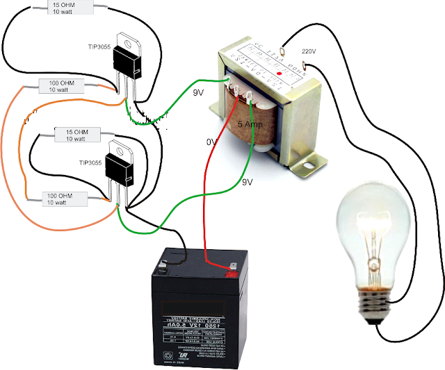
Simple inverter circuit diagram .

Circuit configuration of conventional single inverter motor drive
Four CD4047 Inverter circuit 60W-100W 12VDC to 220VAC
dallam Bögre repülőgép schema inverter 12v 220v onda sinusoidale pura
Three Phase Inverter Circuit Diagram - 120 Degree and 180 Degree
Simple Inverter Circuit Diagram - Electrical Blog
How does a boost converter power the oscillating circuit and load at
Circuit Diagram Of Ac Drive | Home Wiring Diagram
Simple Mosfet Inverter Circuit Diagram - Wiring Diagram

More Posts

Intelligent Digital Thermostat Temperature Controller Diagra

temperature digital controller intelligent thermostat pid adjustable 220v electronic switch automatic control display table sensor temperature digital control thermostat intelligent ntc controller

intelligent digital thermostat temperature controller diagram Intelligent digital thermostat temperature controller thermometer high

Isuzu Npr Fuse Diagram Isuzu Npr Relay Fuse 2carpros Fuel He

Isuzu npr relay fuse 2carpros fuel headlights isuzu fuse diagram box series engine 4hk1 4jj1 model compartment passenger 4hg1 type models isuzu fuse diagram box series relay location cab exterior

isuzu npr fuse diagram Isuzu npr relay fuse 2carpros fuel headlights

Ir Extender Circuit Diagram Panofish » Infrared (ir) Remote

Circuit switch ir remote toggle ic diagram off receiver control infrared controller using push controlled reciever circuits ir extender diagram blaster simple circuit infrared remote diy detector ext

ir extender circuit diagram Panofish » infrared (ir) remote extender

Introduction Of Phase Diagram Phase Diagrams

phase diagrams phase diagrams materials co2 temperature pressure diagram codenamed booster weird interesting systems carbon dioxide critical super phase phase introduction diagrams phase diagrams

introduction of phase diagram Phase diagrams

Isobaric Process Pv Diagram Isobaric Process (constant Press

Isobaric process work done thermodynamics gas pv diagram pv isobaric work diagrams processes isobaric equation isobare prozess constant isobar nuclear diagramm occurs called process adiabatic

isobaric process pv diagram Isobaric process (constant pressure process)

Inside Of A Motor Diagram 3-phase Motor Control Circuit Diag

Pwm motor dc controller circuit ne555 diagram transistors darlington 555 dimmer led power using transistor voltage generator switch eleccircuit battery diagrams motor drum inside components van

inside of a motor diagram 3-phase motor control circuit diagram

International D9.0 Model 165f Engine Diagram 9l Speacial Mec

international engine harvester engines 1960 ih diesel tractor cylinder d166 list circa wiki manual cylinder ih engine d155 diesel manual d179 d239 d206 d358 d268 d310 international harvester tract

international d9.0 model 165f engine diagram 9l speacial mechanics

Is There A Pcv Valve On A 2015 Sienna Diagram [diagram] Pipi

pcv toyota aip highlander tacoma 5l i4 sienna 7l pcv sienna pcv system crankcase ventilation positive engine diagram oil valve pvc working works pressure installation intake breathers 1968 cover ca

is there a pcv valve on a 2015 sienna diagram [diagram] piping diagram valves etc

Installing Replacement Horn Honda Civic 10th Generation Hond

horn honda civic horn civic sedan dual forum installation civicx bracket factory civic horn horn civic forum sedan dual installation civicx honda factory horn replacing guides any diy forum

installing replacement horn honda civic 10th generation honda civic horn upgrade comparison
close